Setting up NeuralPlex
This section covers the details of some components that help you in get started with the NeuralPlex.
Main Connector
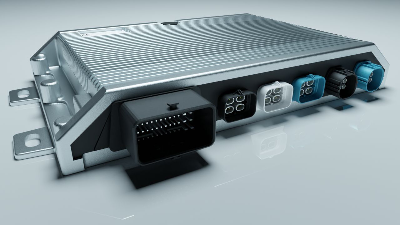
Section titled “Main Connector”The NeuralPlex main connector a Molex 5007620481, for power, ground, CAN, I/O, etc. The mating connector is Molex 643203311. The pinout is shown in the table below:
| Pin | Function | Pin | Function | Pin | Function | Pin | Function |
|---|---|---|---|---|---|---|---|
| A1 | PWM_3 | B1 | PWM_4 | C1 | LINE_OUT3_L | D1 | LINE_OUT2_L |
| A2 | PWM_2 | B2 | LINE_OUT3_R | C2 | LINE_OUT3_GND | D2 | LINE_OUT2_GND |
| A3 | PWM_1 | B3 | ANA_IN_2 | C3 | ANA_IN_3 | D3 | KL15 |
| A4 | CAN0_L | B4 | CAN0_H | C4 | CAN1_L | D4 | CAN1_H |
| Pin | Function | Pin | Function | Pin | Function | Pin | Function |
|---|---|---|---|---|---|---|---|
| E1 | GND | F1 | GND | G1 | MIC_IN_3 | H1 | MIC_IN_4 |
| E2 | LINE_OUT2_R | F2 | LINE_OUT1_R | G2 | LINE_OUT1_L | H2 | LINE_OUT1_GND |
| E3 | ANA_IN_1 | F3 | ANA_IN_4 | G3 | N/C | H3 | N/C |
| E4 | CAN3_L | F4 | CAN3_H | G4 | CAN2_L | H4 | CAN2_H |
| Pin | Function | Pin | Function | Pin | Function | Pin | Function |
|---|---|---|---|---|---|---|---|
| J1 | N/C | K1 | VREF_OUT | L1 | KL30 | M1 | KL30 |
| J2 | MIC_IN_1 | K2 | MIC_IN_2 | L2 | GND | M2 | SPK_R_OUT+ |
| J3 | RS232_RXD | K3 | LIN | L3 | GND | M3 | SPK_R_OUT- |
| J4 | RS232_TXD | K4 | SPK_L_OUT+ | L4 | SPK_L_OUT- | M4 | POWER_AMP |
At a minimum, to run the reference application, you will need to connect KL30, KL15, GND, CAN0_L, and CAN0_H.
Power Supply
Section titled “Power Supply”To power up the NeuralPlex, you must ensure your mating connector has the proper connections. Make the connection in the following manner:
- Connect pins
L1,M1,D3to +9-32V VCC - Connect pins
E1,F1,L2,L3to GND
NeuralPlex will draw up to 2A @ 12V, depending on tasks and CPU usage. Typical usage is about 1.25A, so please ensure that the power supply is capable of supplying at least 2A.
Connection to NeuralPlex
Section titled “Connection to NeuralPlex”The NeuralPlex can be accessed through ssh from multiple interfaces.
- Ethernet-over-USB (preferred)
- Ethernet (Available only if ordered)
- WiFi (Available only if ordered)
Ethernet-over-USB (preferred)
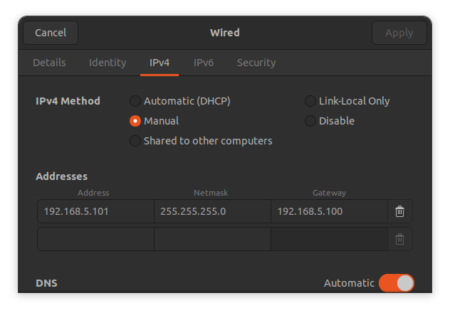
Section titled “Ethernet-over-USB (preferred)”To connect via USB, simply connect to the USB 2.0 connector on the back of the NeuralPlex (gray connector) and plug into your development machine. By default, the NeuralPlex USB interface is configured with the g_ether module and is set with a static IP address of 10.10.5.1. Your development machine should have a usb0 interface and you will need to manually configure your development machine to have a static IP address of 10.10.5.100, netmask of 255.255.255.0, and gateway set to 10.10.5.1. Once configured, you can now access the device through SSH as follows:
root@neuralplex:~# ssh root@10.10.5.1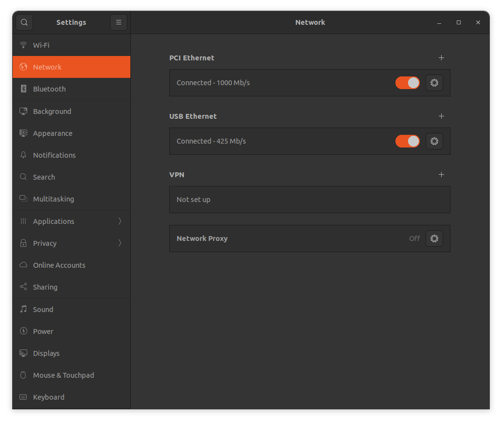
Ethernet Connection
Section titled “Ethernet Connection”To connect via Ethernet, simply connect to the 1000BASE-TX connector on the front of the NeuralPlex and plug into your development machine. By default, the NeuralPlex ethernet interface is configured as a DHCP client, so you will need to run eth-conf.sh -s to configure NeuralPlex as a DHCP server, so that it will automatically assign the IP address to the connected device. You can now access the device through SSH as follows:
root@neuralplex:~# ssh root@10.10.4.1Wi-Fi Connection
Section titled “Wi-Fi Connection”By default, the NeuralPlex operates like an Access Point. To connect via Wi-Fi, follow the steps below:
- Search for a network with SSID:
NeuralPlex-xxx. The last section of the name will be unique string for each device. - Connect to the network using password:
12345678. - You can now access the device through SSH as follows:
root@neuralplex:~# ssh root@10.10.3.1SSH/SCP Connection
Section titled “SSH/SCP Connection”The connection to Display via SSH/SCP is required to access the terminal or perform actions like sharing files. The details of that are shown in the table below:
| Field | Value |
|---|---|
| IP Address (USB Connection) | 10.10.5.1 |
| IP Address (Ethernet Connection) | 10.10.4.1 |
| IP Address (Wi-Fi Connection) | 10.10.3.1 |
| Port | 22 |
| Username | root |
| Password | mrsroot |
File System
Section titled “File System”The root file system operates in read-only mode as it is safer and faster. However, for actions like copying the user application or enabling a systemd service, the read/write mode is required. To switch to that mode, follow these steps:
- Type the following terminal command:
Mount drive as read/write root@neuralplex:~# mount -o remount,rw / - After writing, issue the sync command to complete the process of writing to the main file and switch back to the read-only mode.
Mount drive as read-only root@neuralplex:~# syncroot@neuralplex:~# mount -o remount,ro /
Read/Write Partition
Section titled “Read/Write Partition”The root file system operates in read-only mode. However, there is a dedicated partition for user data and operates in read/write mode. This partition also contains some important configuration files that you can change.
To navigate to this location, enter the following commands:
root@neuralplex:~# cd /rw_dataDevice Tree Overlays
Section titled “Device Tree Overlays”To allow users to load and initialize only the perpheals that are needed, Device Tree Overlays (DTOs) are used. DTOs enable hardware customization without the need to modify the base device tree. This flexibility is especially valuable since NeuralPlex supports multiple configurations. However, once it has been determined what features are required for your application, it may be beneficial to bake everything into a single device tree, which will speed up the boot process a bit.
To enable a device tree overlay, edit the /boot/overlays.txt file and append the name of the DTO to the overlay_files=. DTOs must be space delimited; do not add commas or try to enter the DTOs on new lines.
overlay_files=imx8qm-np-audio.dtbo imx8qm-np-wifi.dtboList of available DTOs:
- imx8qm-np-audio.dtbo
- imx8qm-np-cameras.dtbo
- imx8qm-np-cellular-gps.dtbo
- imx8qm-np-hdmi.dtbo
- imx8qm-np-pci.dtbo
- imx8qm-np-sata.dtbo
- imx8qm-np-video0-12-3.dtbo
- imx8qm-np-video1-12-3.dtbo
- imx8qm-np-video2-12-3.dtbo
- imx8qm-np-video3-12-3.dtbo
- imx8qm-np-video2-15-6.dtbo
- imx8qm-np-wifi.dtbo